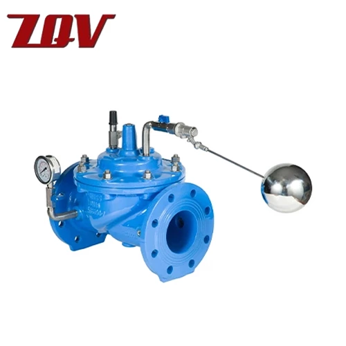
Water Control Valve
Size Range
1/4“ to 2”
Body Materials
A351 CF8M / A216 WCB
Temperature Range
'-50℉ to 450℉ (-46℃ to 232℃)
Stem Materials
A182 F316
Maximum Allowable Operating Pressure
3000 PSI (WOG)
Seat Materials
Delrin / Peek
Body Style
Two Piece
Ball Materials
A182 F316
End Connections
Threaded ASME B1.20.1 NPT
Design Standard
ASME B16.34 , MSS SP-110
Ports
Full Port
Testing Standard
MSS-SP72,API 598
Applications
General Service, Air, Water, Oil & Gas
Face to Face
Manufacturers Standard
Description
Installation of water control valve
When installed horizontally, the valve cover should be upward. There shall be drainage facilities behind the pressure reducing valve of the fire water supply system. When the pressure of the automatic sprinkler system needs to be reduced, the pressure reducing valve shall be set in front of the alarm valve (along the water flow direction). The pressure reducing valve matched with a single alarm valve may not be used for the equipment; The pressure reducing valve matched with multiple alarm valves shall be the plant pressure reducing valve of the equipment. Pressure reducing valves for hot water supply works shall be hot water type.
Material of main parts
» Valve body: cast iron, cast steel, stainless steel
» Sealing ring: nitrile rubber
» Valve plate: ductile iron, cast steel
» Bonnet: cast iron, cast steel, stainless steel
» Guide sleeve: ductile iron, brass
» Diaphragm: nitrile rubber
» Stem: stainless steel
» Compression spring: stainless steel
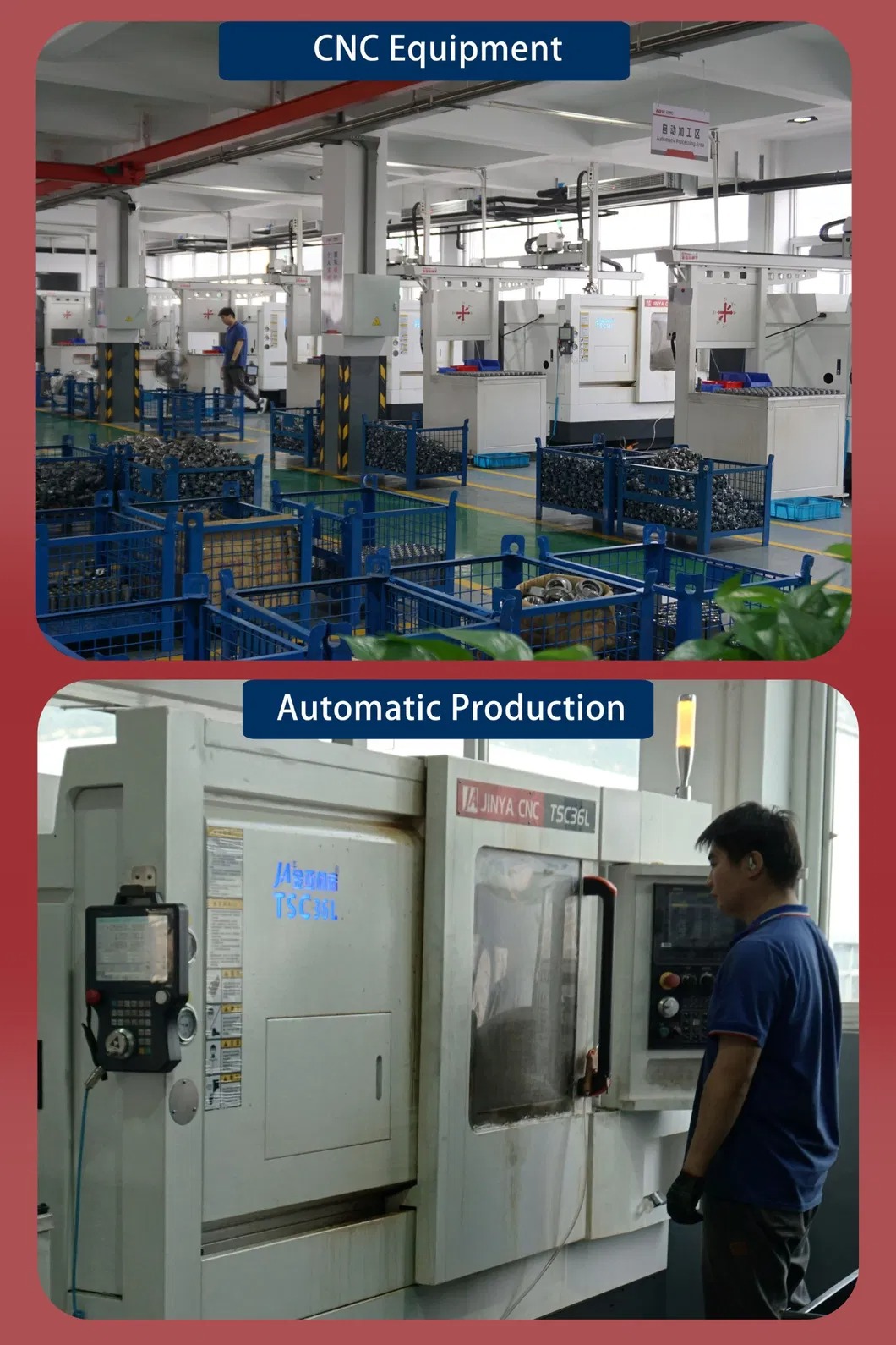
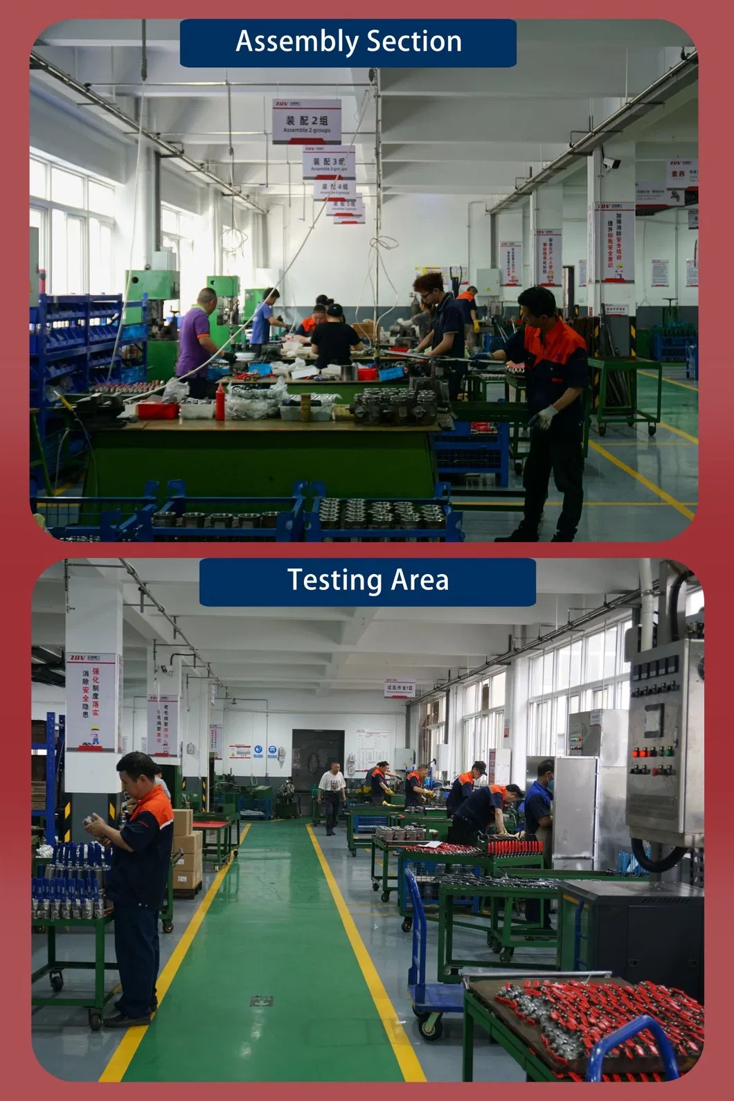
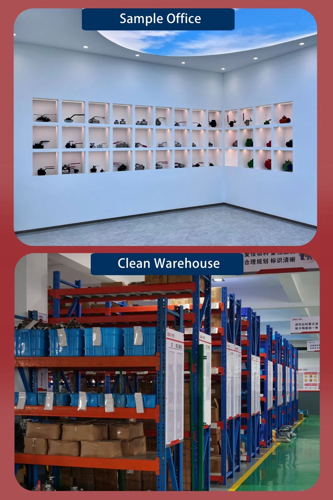
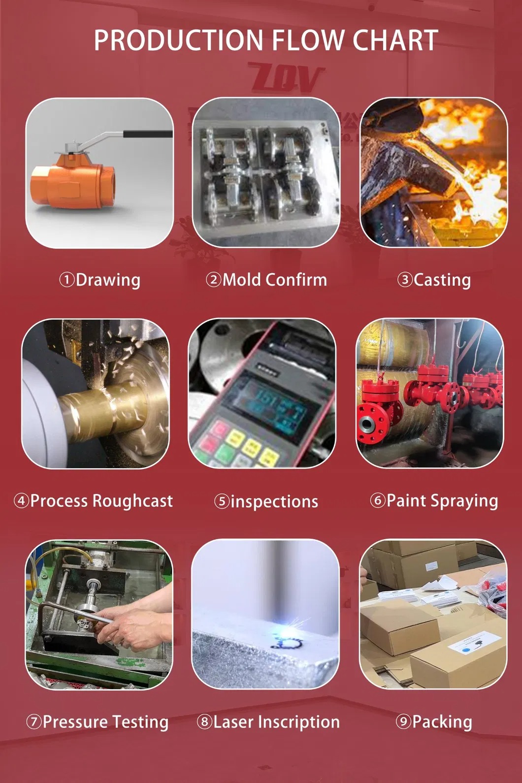
Factory Show